

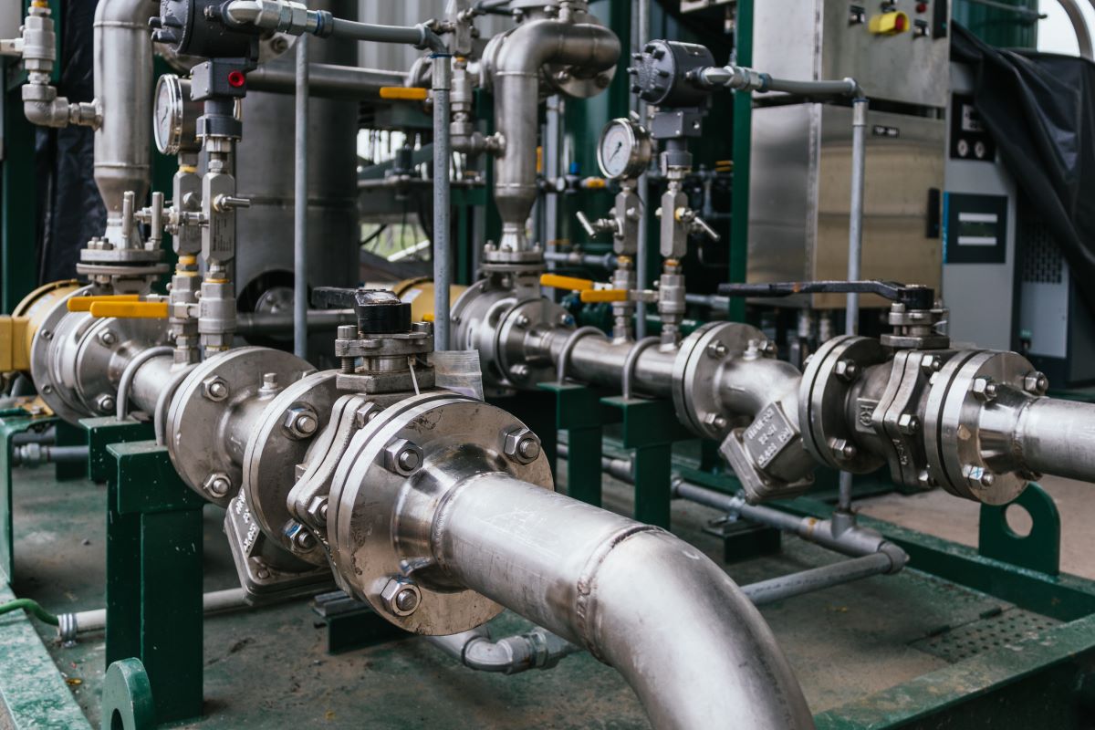
In industrial facilities, pressure exceeding the specified operating limits can lead to equipment damage, production losses, and serious safety risks. Therefore, pressure control, relief capacity, and the operating conditions of protective equipment should be evaluated together during system design. In particular, a pressure relief valve helps protect the system by releasing excess fluid in a controlled manner when the allowable pressure limit is exceeded. However, a safe process depends not only on selecting the right equipment but also on engineering calculations, proper installation, regular maintenance, and continuous monitoring of operating conditions.
What Is Overpressure in Industrial Systems?
Overpressure occurs when a tank, pipeline, pressure vessel, or process equipment operates above the safe pressure limit established during the design stage. Every piece of equipment is designed to withstand a specific pressure based on its material, geometry, connection type, and operating conditions. Exceeding these limits may compromise the structural integrity of the equipment.
Normal operating pressure and the maximum allowable working pressure of the equipment are different values. Operating a system too close to its safety limit under normal conditions may cause even a minor process change to create a significant risk. Therefore, normal operating values, temporary pressure fluctuations, and potential failure scenarios should be considered together during the design stage.
Early detection of rising pressure is essential, but it is equally important to transfer excess fluid to a safe location until the condition causing the pressure increase is eliminated. Pressure control and relief solutions create two separate layers of protection that complement each other.
What Causes Overpressure?
Overpressure in industrial systems may result from more than one cause. A blocked outlet line, an incorrect valve position, a control system failure, or a pressure increase caused by a pump or compressor are among the most common reasons. Operator errors and unexpected changes in process conditions may also increase system pressure.
An increase in the temperature of a liquid trapped in a closed volume can lead to a significant rise in pressure due to thermal expansion. In heat exchangers, tube rupture may expose the low-pressure side to higher pressure. In the event of a fire, heating and vaporization of the fluid inside a tank may create a critical scenario requiring high relief capacity within a short period.
Runaway chemical reactions, power failures, cooling system shutdowns, and irregularities in steam lines should also be taken into consideration. During risk assessment, not only normal production conditions but also start-up, shutdown, maintenance, and emergency conditions should be examined.
How Does Overpressure Affect Equipment and Plant Safety?
An uncontrolled increase in pressure may cause seal leakage, deformation at connections, cracks in pipelines, or structural damage to pressure vessels. In systems containing flammable, toxic, or corrosive fluids, even a minor leak may have serious consequences for employees, the environment, and the production area.
In addition to equipment damage, unplanned downtime, product losses, and maintenance costs may affect operational continuity. Damage to a single component may require other connected process equipment to be shut down as well. This can result in production delays and reduced energy efficiency.
Protection systems are designed to reduce the severity of the consequences caused by overpressure. However, these systems must be compatible with process conditions and provide sufficient capacity under the most critical potential scenario.
How Do Pressure Relief Systems Work?
The primary purpose of pressure relief systems is to provide a controlled discharge path for excess fluid when system pressure reaches a specified level. Protective equipment remains closed during normal operation. When the pressure reaches the set level, the equipment opens and allows gas, vapor, or liquid to flow into the discharge line.
Once the pressure falls to a safe level, the equipment closes again and helps the process continue under controlled conditions. Opening and closing behavior may vary depending on the equipment design, fluid properties, inlet pressure, and back pressure in the discharge line.
The discharged fluid may be directed into the atmosphere, a closed collection system, or a flare system. The appropriate discharge method should be determined by considering the fluid’s flammability, toxicity, temperature, and potential environmental impact.
How Is the Right Safety Equipment Selected?
Selecting safety equipment based only on connection size or operating pressure is not sufficient. The fluid phase—gas, vapor, or liquid—as well as its temperature range, viscosity, corrosive properties, and solid particle content should all be evaluated.
The set pressure, allowable pressure limits, and normal operating range of the process must be compatible with one another. During material selection, the resistance of the body, spring, disc, seals, and other fluid-contact components to the process environment should be verified. Inappropriate materials may lead to corrosion, loss of sealing performance, or sticking of moving components.
Applicable engineering standards, plant specifications, and manufacturer data should be evaluated together during the selection process. This approach helps create a technically compatible and sustainable solution for the process.
How Are Capacity and Sizing Calculations Performed?
The purpose of sizing calculations is to determine the amount of fluid that must be relieved under the most critical overpressure scenario. Potential scenarios such as a blocked outlet, fire exposure, thermal expansion, control valve failure, or heat exchanger tube rupture should first be analyzed.
Once the required relief flow rate has been determined, fluid properties, inlet temperature, set pressure, back pressure, and discharge conditions should be included in the calculation. The calculation methods used for gas and vapor applications may differ from those used for liquid applications.
An undersized relief area may prevent pressure from being reduced quickly enough. Oversizing, on the other hand, may cause unstable operation, frequent opening and closing, and mechanical wear. For this reason, sizing calculations should be based on applicable standards and verified process data.
How Should Pressure Relief Equipment Be Installed?
Even correctly selected equipment may fail to deliver the expected performance if it is installed improperly. The inlet line should be kept as short and direct as possible. Unnecessary elbows, restrictions, and connections that may create excessive pressure loss should be avoided.
The discharge line should be designed by considering the back pressure that may occur during flow. Loads caused by the weight of the piping system and thermal expansion should not be transferred to the equipment. In applications requiring drainage, appropriate arrangements should be made to prevent liquid accumulation.
The installation orientation, support method, and flange connections should comply with the manufacturer’s instructions. Before commissioning, the line should be cleaned to prevent welding debris, foreign materials, and installation residues from reaching moving components.
Why Are Periodic Maintenance and Testing Necessary?
Protective equipment may remain inactive for extended periods; however, it must open at the correct set pressure when required. Corrosion, deposit buildup, changes in spring characteristics, and wear on sealing surfaces may affect performance over time.
Maintenance intervals should be determined by considering fluid properties, process criticality, operating conditions, and previous test results. During inspections, the set pressure, sealing performance, moving components, and material condition should be examined. Completed tests and replaced components should be properly documented.
Regular maintenance contributes not only to process safety but also to reducing unplanned downtime. Kiatork supports the design of safe and sustainable systems by providing pressure relief solutions suited to the operating conditions of various industrial applications. When proper design, suitable equipment selection, professional installation, and traceable maintenance processes are considered together, a reliable protection system against overpressure can be established.


