API 526 Series (Spring Loaded)
A spring-loaded valve is a self-actuating safety relief valve that operates using a spring mechanism designed to open at a predetermined pressure. Spring-loaded valves include traditional, balanced diaphragm, and balanced piston types. These valves are flanged and comply with the API 526 standard. Their sizes range from 1″x2″ to 8″x10″ and have flange ratings between #150×150 and #2500×300.
Explanation
A spring-loaded safety relief valve or direct-acting spring-loaded valve is a self-operating spring-loaded pressure relief valve designed to open at a predetermined pressure and protect a vessel or system from overpressure by discharging or venting fluid from that vessel or system.
These types of safety valves meet all the requirements of API 520, API 521, API 526, PED/EN ISO 4126, GOST 31294, and GOST 12.2.085, such as orifice area, sizing procedure, size, pressure ratio, and flange connection size.
Traditional Safety Relief Valve: The traditional pressure relief valve is a spring-loaded pressure relief valve whose operating characteristics are directly affected by changes in back pressure.
Balanced Safety Relief Valve: A balanced type safety relief valve is a spring-loaded pressure relief valve that incorporates a bellows or other device to minimize the effect of back pressure on the valve’s operating characteristics.
Advantages:
- 100% Compliance with API 526
- Adjustable blowdown
- The most reliable type when correctly sized and operated
- Versatile, usable in many services
Applications: Provide the highest level of protection against overpressure in all applications involving steam, gas, and liquids.
- Refineries
- Chemical industry
- Petrochemical industry
- Oil and gas – Onshore and offshore
- Ships and pipeline systems
- Blowdown systems
- Storage tank farms
How does it work?
How a Safety Relief Valve Works – Step by Step
Safety relief valves use spring force to hold the disc in place. Under normal operating pressure, the spring force exceeds the inlet pressure force, keeping the valve closed. The valve opens when the system pressure exceeds the spring force.

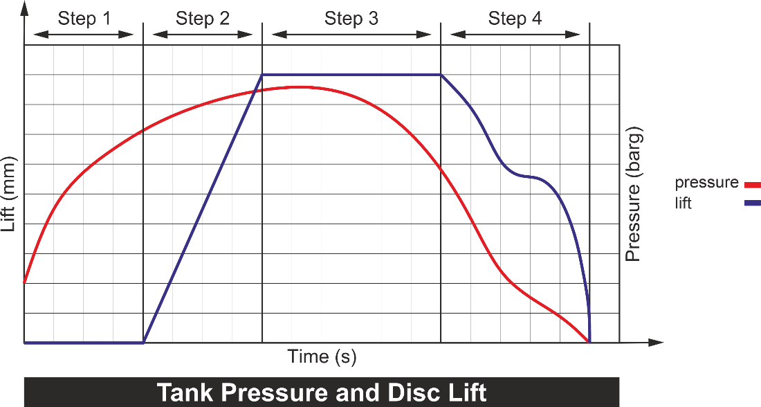
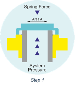
Step 1: Valve Closed (Normal Operation)
• Condition: Inlet Pressure < Set Pressure
• Mechanism:
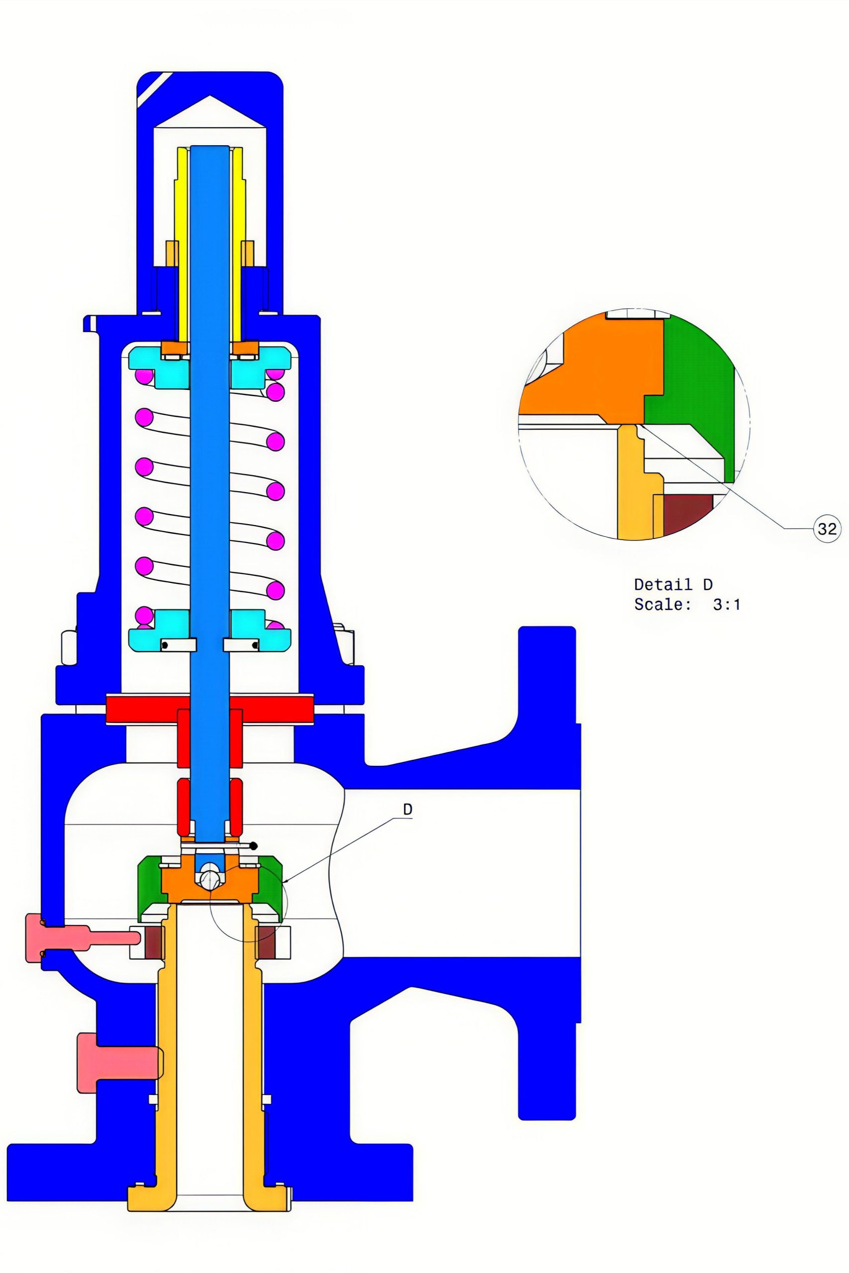
• System pressure acts on the disc surface (area "A")
• Spring force resists this pressure
• As system pressure approaches the set pressure, the seating force between the disc and nozzle nears zero

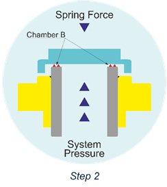
Step 2: Valve Slightly Open (Pre-Opening Phase)
• Condition: Inlet Pressure ≥ Set Pressure but < Popping Pressure
• Mechanism:
1. In vapor or gas service, the valve may slightly open before fully popping.
2. Fluid begins to move audibly into the accumulation chamber "B"
• Flow restriction between the disc holder and adjusting ring causes pressure buildup in "B"
3. This buildup creates an expanding force that helps overcome the spring
4. The adjusting ring can be tuned to control pressure accumulation
5. Once the accumulated pressure exceeds the spring force, the disc lifts and the valve pops open

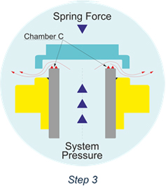
Step 3: Valve Fully Open (Popping Phase)
• Condition: Inlet pressure ≥ Popping pressure
• Mechanism:
1. Additional pressure forms at point "C".
2. Sudden flow increase through the annular gap between the inner edge of the disc holder skirt and the outer diameter of the adjusting ring
3. These forces cause the disc to lift significantly during the pop

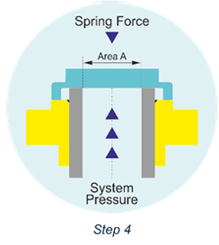
Step 4: Valve Reseats (Closing Phase)
• Condition: Inlet Pressure drops below reseating pressure
• Mechanism:
1. When inlet pressure falls sufficiently below the set pressure, the valve closes
2. Spring force overcomes the combined forces at points "A", "B", and "C"
3. The pressure at which the valve reseats is called the reseating pressure
4. The difference between the set pressure and reseating pressure is known as blowdown
Technical Information
| Type | Api 526 Serisi – Metrik (Conventional-Balanced Bellows) | Api 526 Serisi – SI (Conventional-Balanced Bellows) |
|---|---|---|
| Inlet size range | DN25-DN200 | 1″-8″ |
| Outlet size range | DN50-DN250 | 2″-10″ |
| Connection STD | DIN 1092-1 | ASME B16.5 |
| Inlet flange rating | PN20-PN420 | CL 150-CL2500 |
| Orifice Letter | D-T | D-T |
| Pressure range | Acc. To API 526 | Acc. To API 526 |
Standards and Codes
| ISO 9001 | International standard for quality management systems |
| ASME Section VIII | Rules for construction of pressure vessels (Part 1 & 2) |
| API | American Petroleum Institute – industry standards for oil and gas equipment |
| API 520 | Sizing, selection, and installation of pressure-relieving devices (Part I & II) |
| API 526 | Flanged steel pressure relief valves |
| API 527 | Seat tightness testing for pressure relief valves |
| EN ISO 4126-1 | Safety valves – European and international standard |
| ANSI | American National Standards Institute – general standards body |
| ANSI B16.50 | Pipe flanges and flanged fittings |
| NACE MR 01-75 | Metallic materials resistant to sulfide stress cracking in oilfield equipment |
| 2014/68/EU | Pressure Equipment Directive (PED) – European regulation for pressure equipment |


